
The Basics of Rocket Engine Plumbing
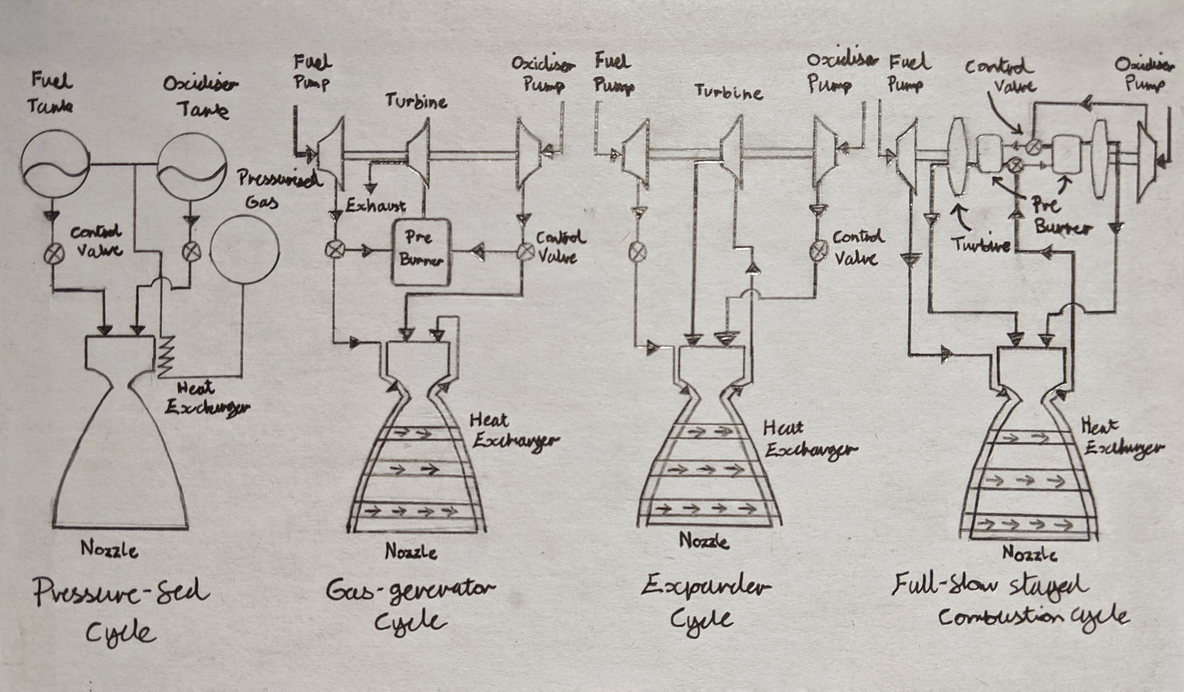
An ‘artistic’ rendition of engine cycles
As I’ve been reading more about software design patterns, I recalled a bit of reading I did during university on rocket engines cycles and how the topic could be thought of in similar terms to a design pattern. The concept of a program’s pattern referring to a well recognised way of solving a particular problem. Businesses typically like to implement them in their software designs due to the benefits:
- A new but experienced engineer can draw on their existing knowledge of patterns and therefore quickly understand the solution being used
- Common patterns often have their advantages and disadvantages well explored, reducing time spent testing system behaviour
- Adhering to a design pattern often forces a reduction in unnecessary system complexity
Patterns can infact be applied to almost any problem within an engineering context but I thought I’d take the opportunity to jot down what I gathered about the various patterns used to design rocket engines.
First to cover a few basics. Key to a rocket’s ability to take-off is the rate at which mass is thrown out the back of it. Contrary to a jet engine creating forward motion in order to generate lift over the vehicle’s wings, rocket engines rely purely on expelling mass at a high velocity to generate upward motion. A higher rate of expulsion will produce a larger downward force and calling back to Newton’s third law, a larger upward reactionary force on the launch vehicle. We can refer to this reactionary force as thrust - which ultimately launches the rocket on its trajectory.
In rocketry the total change in velocity brought about by using the entirety of a rockets fuel is referred to as ‘Delta-v’ and is used as a measure of a rocket’s power. Depending on the mission objectives different Delta-v’s are needed to perform different maneuvers - a trip to Mars for example would require a much higher Delta-v than injection to Low Earth Orbit.
Do rockets really have ‘design patterns’ as well?

Falcon Heavy’s roaring Merlin Engines (SpaceX)
To achieve high Delta-v’s rocket typically use liquid propellants due to liquid’s high energy density which allows for a more mass efficient rocket over solid propellant alternatives. Although various liquid mixes can be used to power a rocket, in practice bipropellant rockets are the most common meaning the dual use of liquid fuel and liquid oxidiser, which we will focus on.
Key to utilising liquid fuel’s high energy density is an engine’s ability to consistently supply the combustion chamber with propellants at high pressures and high specific mass flow rates. Rocket engines supply themselves the energy required to do this via feed systems which can be thought of as an engines internal plumbing.
“Liquid propellant feed systems consist of piping, a series of valves, provisions for filling and usually also for removing (draining and flushing) the liquid propellants, filters, and control devices to initiate, stop, and regulate their flow and operation” — George P. Sutton, Rocket Propulsion Elements
These systems are predominantly powered by either high-pressure gas or turbopumps but importantly there is no ‘one size fits all’. Almost every engine has a different feed system, each of which provides its own design benefits and drawbacks, similar to the design pattern analogy drawn on earlier. So let’s explore some of the most common feed systems and do a general comparison between them.
Pressure-fed Engines:
Pressure-fed engines are the simplest and most reliable feed systems in use. Fundamentally, these systems use a separate supply of very high-pressure gas, usually inert such as helium, to force propellant from its tanks into the combustion chamber. As a result, the plumbing required is simple typically comprising of a gas starting valve, a gas pressure regulator, propellant tanks, propellant valves, feed lines and a high-pressure gas tank.
Not your typical engine, Pixel was a pressure-fed Lunar Lander vehicle (ArmadilloAerospace)
The system can be simplified further by removing the high-pressure gas tank and instead storing the high-pressure gas at the top of the propellant tanks themselves. This is called a ‘blow-down’ pressure-fed system in contrast to a ‘regulated’ pressure-fed systems described prior. As well as simplifying the design ‘blow-down’ systems often requires less gas and allows for a less inert gases to be used in the system. However, a major downside of the ‘blow-down’ system is that the pressure varies over time. Meaning the propellant flow rate to the combustion chamber decreases over time whereas a ‘regulated’ system does not suffer from such an issue.
In general pressure-fed engines are the best choice for missions where both the required Delta-v and rocket payload is low. This is due to their best-in-class efficiency, cost and reliability at such mission specifications. During SpaceX’s infancy, they opted for a ‘regulated’ pressure-fed system in their Kestrel engine, used in the upper stage of the Falcon 1 launch vehicle, crucial for achieving system simplicity and driving down costs.
For missions with heavier payloads, higher Delta-v’s or both, the engine must generate more thrust which demands an increase in combustion chamber pressure. To produce higher pressures in a pressure-fed system, larger and more reinforced tanks are required which greatly increases the mass of the rocket. This makes pressure-fed systems hard-sells and is why many engine designs turn to turbopump feeds.
Advantages:
- Simplistic and low cost design
- Engines typically produce a high specific impulse (thrust per unit mass of propellant used)
Disadvantages:
- Generally low Delta-v’s due to pressure limits imposed by feed gas
- Necessitates use of heavy gas tanks
Turbopump-fed Engines:
In contrast to pressure-fed engines, turbopump engines use the expansion of high enthalpy gases to drive turbines that power propellant pumps to the combustion chamber. This added complexity allows for high chamber pressures without significantly increasing the weight of the rocket, unlike pressure-fed systems.
The way the turbine in a turbopump receives energy can vary and is referred to as the engine cycle. Although there are several engine cycles, most are variations on three common engine cycles: gas-generator cycle, expander cycle and staged combustion cycle.
Another key distinction is whether an engine cycle is open or closed. Open cycles discharge the working fluid coming from the turbine, usually out of the nozzle. Closed cycles instead use all working fluid by burning it all in the combustion chamber.
Gas-generator cycle:
By far the most common form of turbopump engine cycle used is the gas-generator cycle. A separate gas-generator, also referred to as the pre-burner, is used to power the turbine of the turbopump. The propellant used to generate inlet gas for the turbine is usually drawn from the main propellant pumps via control valves.
The gas is then discharged to the atmosphere separately from the combustion chamber. This has the benefit of allowing the turbine flow-path to run in parallel with the combustion chamber flow-path, separating the two functions. As a result, the complexity of the engine is greatly reduced as there is no need to deal with the counter pressure of the exhaust discharging into the combustion chamber.
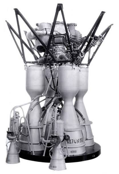
RD-107 gas-generator engine powers Russia’s famous Soyuz rockets (NPO Energomash)
Given a gas-generator expands to atmospheric pressure there is a large pressure ratio across the turbine and thus a high available energy per unit mass of flow across the turbine. Combined with an overall efficient turbopump and high thermal operating temperature, a low turbine flow rate can produce a high specific impulse.
The caveat to this is gas-generator cycles are by definition open cycles, meaning not all propellant that can be burnt in the combustion chamber is. This results in losses in overall specific impulse. Moreover, most gas-generators operate on fuel-rich mixes such that gas temperatures are low enough to allow for use of uncooled turbine blades. This has a knock-on effect on the combustion chamber which balances the effect of a fuel-rich turbine exhaust by changing the combustion chamber’s chemistry, further reducing the total specific impulse.
Advantages:
- Although more complex than pressure-fed engines, the two-system design remains simplistic
- Reliable choice for ensuring a high thrust engine
Disadvantages:
- Generally low specific impulse versus counterparts
- Recycling secondary exhaust through the nozzle adds the extra complexity of back-pressure
Expander cycle:
The expander cycle is in contrast a closed engine cycle meaning all fuel is burnt in the combustion chamber. Cryogenic fuel is pumped around the combustion chamber and nozzle acting as a coolant picking up heat. The fuel once hot, changes phase to a gas and powers the turbine of the turbopump. As well as closing the cycle this design has the added benefit of removing the gas-generator and its accompanying plumbing making the cycle much cheaper and more reliable.

VINCI is a fresh attempt at a high performance Expander Cycle engine (ESA)
Several expander cycle engines have been successfully flown in the past with the RL10 engine being the most notable, having flown multiple missions with a very reliable track record. Currently ESA is developing a state-of-the art expander cycle engine called the VINCI which uses two separate turbopumps and a long combustion chamber to capitalise on a larger surface area. This will supposedly allow the VINCI to double the thrust output of the RL10.
However, the thrust of the expander cycle is limited by the geometry of the rocket engine as a result of the square-cube law. Meaning increasing the radius by a factor of 2 would increase surface area by a factor of 4 but volume by a factor of 8. As a result, there is a maximum threshold at which there is no longer sufficient surface area to heat enough fuel to drive the turbopump at the required flow rate.
Advantages:
- Simplest design of all engines mentioned
- Engines typically produce a high specific impulse
Disadvantages:
- Necessitates use of cryogenic fuel, not suitable for all missions
- Square-cube law imposes a thrust limit on these designs
Staged combustion cycle:
The final notable turbopump engine cycle is the staged combustion cycle, a closed cycle, high performance and high thrust engine cycle that comes with the trade-off of greatly increased complexity. Opposite to gas-generator cycles, the pre-burner and turbine flow-path is in series with the combustion chamber flow-path and thus experiences counter pressures of the exhaust being discharged into the combustion chamber.

Starship fitted with SpaceX’s powerful full-flow staged combustion Raptor Engines (SpaceX)
As a result, staged combustion engines have more complex plumbing and more resilient turbines to withstand the higher-pressure engine environment. Moreover, the newly introduced feedback between the pre-burner and combustion chamber makes the engine significantly harder to start-up correctly.
Full-flow staged combustion cycles are most complex staged combustion cycles but boast the most impressive performance and thrust characteristics of all cycles. SpaceX’s next generation Raptor rocket engine, which will power the famous Starship to Mars, is a full-flow staged combustion cycle methalox engine.
Advantages:
- Highest specific impulse currently possible
- Engines are typically high thrust
Disadvantages:
- Performance benefits are at the expense of a high complexity and high cost design
- The additional plumbing involved makes stages engines hard to start-up
That’s it!
It is important to note that feed systems are not limited to those discussed here, hybrids, variations and completely new feed systems are constantly being developed. Electric feed systems such as the one used in Rocket Lab’s Rutherford engine are examples of this, showing major promise in rivalling incumbent feed system designs over the next decade.
Otherwise, that’s it we’ve taken a look at the simplified engineering behind the most common bipropellant feed systems and evaluated the various engineering trade-offs between each.